Tel : +86-577-62665555
+86-577-62668988
Business Email : [email protected]
ZW30-40.5 Series of outdoor high voltage vacuum circuit breakers
 Published in2018-08-04
 5708 Views
Detailed description
Overview
ZW30-40.5 Series of outdoor vacuum circuit breaker, 40.5KV is an outdoor breaker developed by my Co. with the international 90s level. It is designed for used in power plants, substations and other major power stations as control and protection of power equipment and power lines, and can also be used for frequent operation sites. It is the first choice of power switch equipment for new substation.
Product application and operation conditions
Normal operation Conditions
--- Altitude: 1000M; 4000M (grade II polluted area)
--- Wind speed: no more than 700Pa (equivalent to 34M/s);
--- Seismic intensity: no more than 9 degrees;
--- Degree of air pollution: Grade III;
--- Product features: the sealing structure is filled with 0.02Mpa (20℃)high purity nitrogen gas(or SF6 gas) to ensure that it will not coagulate internally under any climatic conditions. Because the product adopts high pressure sealing structure with superior sealing performance. It is only 0.02MPA gas so that internal and external pressure are quite close, so possibility of leakage is completely eliminated.
--- Using high purity nitrogen gas(or SF6 gas) as an insulating medium, it completely solve internal breakdown due to gas blowholes (bubbles) which are made by using filled silicone grease or epoxy resin casting and difficulties of maintenance of external current transformer. Each current transformer can choose four different secondary parameters (that is equivalent to 12 sleeve typed current transformers). And it can meet requirements of users for accuracy of all current level, and the current transformer can be connected to end of incoming line or outlet end.
Technical parameters
Table 1
|
Serial No. |
Name |
Unit |
Parameters |
|||||
|
1 |
Rated voltage |
KV |
40.5 |
|||||
|
2 |
rating current |
A |
400/630/800/1250/1600 |
|||||
|
3 |
rating short circuit breaking current |
KA |
20/25/31.5 |
|||||
|
4 |
rated short circuit current (peak) |
KA |
80 |
|||||
|
5 |
nominal short-time tolerance current |
KA |
31.5 |
|||||
|
6 |
rated short circuit duration |
s |
4 |
|||||
|
7 |
rating peak tolerance current (peak) |
KA |
80 |
|||||
|
8 |
Rated frequency |
Hz |
50/60 |
|||||
|
9 |
Rated insulated level |
1 min power frequency tolerance(effective value) |
dry test withstand voltage |
Cross-open contacts / phase to earth |
KV |
95/95 |
||
|
wet test withstand voltage |
Cross-open contacts / phase to earth |
KV |
80/80 |
|||||
|
lightning impulse tolerance (peak) |
Cross- open contacts / phase to earth |
KV |
185/185 |
|||||
|
10 |
first open pole coefficient |
|
1.5 |
|||||
|
11 |
rated off-step break current |
KA |
8 |
|||||
|
12 |
rated a capacitor group open breaking current |
A |
630 |
|||||
|
13 |
short circuit break rated operation sequence |
|
0-0.3s-CO-180s-C0 |
|||||
|
14 |
rated short circuit breaking times |
Ops |
20 |
|||||
|
15 |
mechanical life test times |
Ops |
10000 |
|||||
|
16 |
circuit breaker weight |
kg |
750 |
|||||
|
17 |
rated charging pressure (filling nitrogen or SF6) |
MPa |
0.07 (20℃) (external CT) ; More than 0.3 (built-in CT) |
|||||
|
18 |
Running gas pressure under 20℃ |
MPa |
0~0.07 |
|||||
|
19 |
creepage ratio |
Mm/KV |
31 |
|||||
Table 2
|
Serial No. |
Names |
Unit |
Parameters |
|
1 |
contact line distance |
mm |
25±2 |
|
2 |
Contact traveling distance |
5±2 |
|
|
3 |
average closing speed(before contact buffer) |
M/s |
1.7~2.2 |
|
4 |
average closing speed |
0.6~1.0 |
|
|
5 |
contact closing bouncing time |
ms |
≤ 10 |
|
6 |
Opening synchronization between poles |
≤1 |
|
|
7 |
Closing synchronization between poles |
≤2 |
|
|
8 |
Closing time |
≤90 |
|
|
9 |
Fixed opening time |
35~65 |
|
|
10 |
circuit resistance of per pole |
|
≤50 (external CT) |
|
11 |
Centre distance between poles |
mm |
710/720/750 |
Overall structure characteristics of the circuit breaker
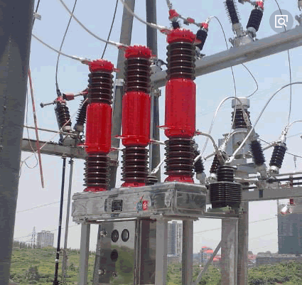
The breaker is generally composed of upper porcelain bushing, lower porcelain sleeve, low rack and operation mechanism. Vacuum interrupter is installed in upper porcelain bushing, and arc extinguishing chamber is made of ceramic shell and exposed stainless steel shielding cylinder, and contact is made of CUCR50 material and cup shaped longitudinal magnetic field. Bottom line of the circuit breaker uses a slider type intermediate contact, circuit resistance is small, and electrical conductivity is very good. Lower porcelain sleeve is insulation pillar, electric part is insulated to ground, and porcelain sleeve is equipped with a insulated pulling bar.
Each current transformer can choose four different secondary parameters (that is equivalent to 12 bushing current transformers). And any current level accuracy can meet user requirements, transformer can be inserted into the end of the line or outlet, and do not interfere with one or two times (Figure 1).
The upper and lower porcelain bushing is filled with 0.02MPA (20℃)high purity nitrogen(orSF6 gas). The lower part of the mechanism box is equipped with the latest CT19 mechanism, the two outlet terminal and the gas pressure gauge of the current transformer.
---- Product outline dimensions and installation dimensions are shown in Figure 1 (internal CT see attachment drawings).
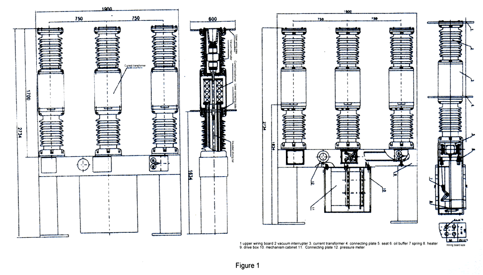
Note: Air pollution level of antifouling type is IV grade, and the plateau environment is 40m below sea level.
Circuit breaker gas charging instructions: the sealing structure is filled with 002MPA (20℃) SF6 gas (or high purity nitrogen) to ensure no condensation inside any climatic conditions. Because the product adopts high pressure sealing structure with excellent sealing performance, only 0.02MPA gas and internal and external pressure are quite close, so the possibility of leakage is completely eliminated. 0.02MPA (20℃) gas, not zero pressure meter gas (even if the product gas is zero pressure meter, still can ensure safe operation), one is to facilitate monitoring (can be read directly by the pressure meter), the two is to prevent low temperature negative pressure. When the ambient temperature exceeds (or below) 20℃, the pressure gauge reading is slightly larger than (or less than) the rated air pressure. For operation and maintenance, cocoa is also charged to 0.02MPA~0.04MPA without affecting the performance of the product. The CT19 spring operating mechanism used for circuit breaker is shown in Figure 2. The electrical principle of the mechanism is shown in Figure 5.
---- Operation mechanism
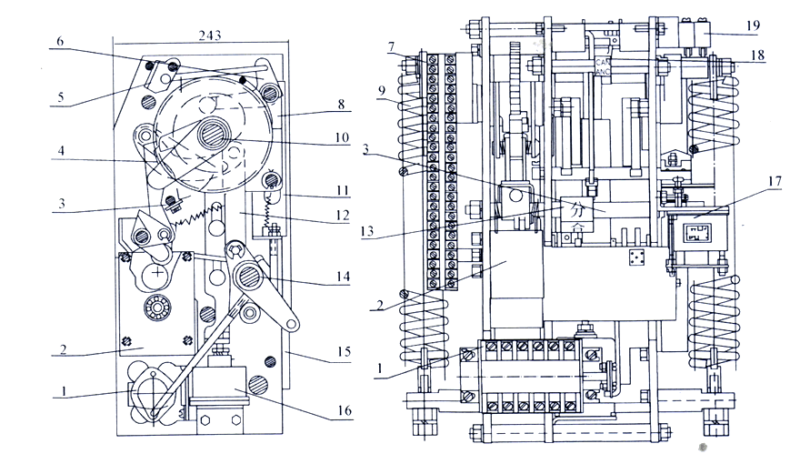
1 . Auxiliary switch, 2. energy storage motor , 3. semi shaft, 4. drive pawl, 5. button,6. Position part, 7. connection terminal, 8. holding pawl, 9. closing spring,
10. energy storage shaft, 11. switch interlocking plate, 12. closing joint-connecting rod,13.On/Off sign plates, 4. output axle shaft, 15. angle steel, 16. interlocking electromagnet
17. Over-current release & open electromagnet, 18. storage energy indicator, 19 stroke switch.
Other Similar Products
-
FLW-12/24/40.5 series of Pole mounted SF6 Load break switch
-
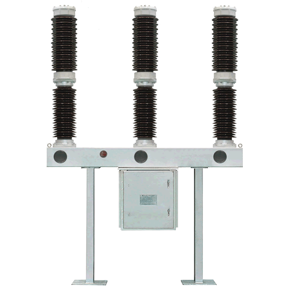
LW36-72.5 / 126 Outdoor HV. AC. SF6 circuit breaker
-
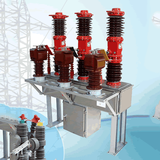
ZW30-40.5 Series of outdoor high voltage vacuum circuit breakers
-
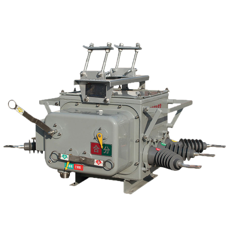
ZW20-12 Series outdoor high-voltage vacuum circuit breaker
-
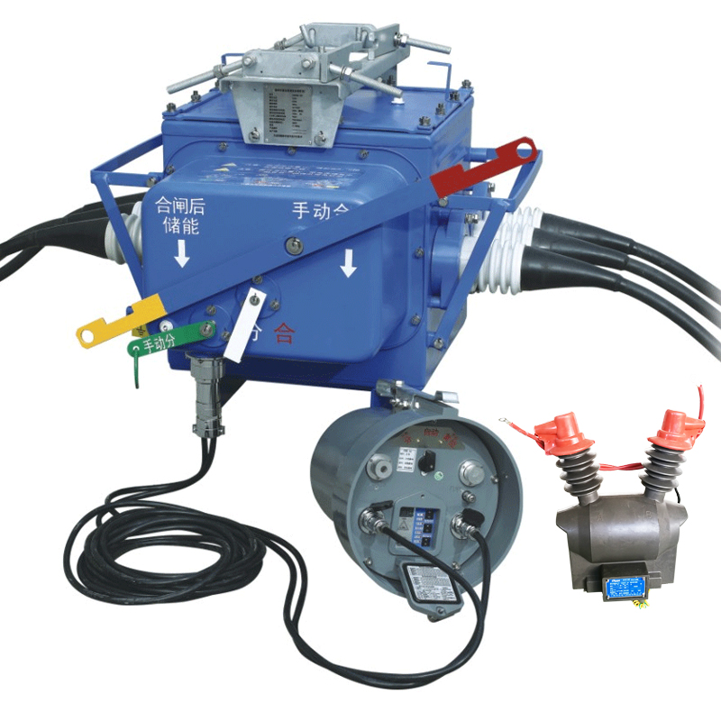
FZW28-12F series AC high voltage demarcation vacuum automatic recloser

